User Manual of MTF Configuration File
MTF Core requires assigning logical channels to physical channels to specify which hardware interface/channel has to be used for data reception and transmission. MTF Core config file (yaml file) defines such assignment.
This config file is composed of three main sections:
Channels: Defined logical (software) channels, accessible from the framework or test cases. A channel can for instance be a Bus, IO (input/output) , a serial port, etc.
Mappings: HW channels to Logical channels mapping.
FrameworkConfig: Tracers configuration, internal modules configuration, etc.
Channels
Logical (software) channels, accessible from the framework or test cases:
‘ChannelName’ + Id: A channel must have a unique ID and name.
Alias: A channel can have several aliases (e.g. CAN_channel have as aliases Ch_CAN or Chan_CAN).
Type: A channel has a specific type (CAN, LIN, FR, ETHERNET, IOOUTPUT, IOSERIAL, PS, BRIDGE).
Protocol: A channel can have a protocol version. In case the logical channel is a bus system. This field indicates the Protocol version (e.g. CANFD, CAN2.0, CAN-IB500, CANFD-IDENTICAL-ArbPh-DataPh (BRS = 0 for all Tx Request), LIN1.3, LIN2.2).
LoggingName: A channel can have a specific logging name (used only for ascii tracing).
LoggingBusIndex: A channel can have a specific logging index (used only for ascii tracing).
TracerName: A channel can be associated to a specific tracer. This tracer is used for logging the incoming and outgoing traffic or measurements. For example, this allows us to trace the traffic of a specific channel to a particular Trace.
Channels:
 CAN_channel:
  Id: 1
  Type: CAN
  Protocol: CAN2.0
  loggingName: CAN_channel
  Alias: [Ch_CAN, Chan_CAN]
 CAN_FD_channel:
  Id: 2
  Type: CAN
  Protocol: CANFD
  Alias: [Ch_CAN_FD]
 ETH_SOMEIP:
  Id: 3
  Type: ETHERNET
  TracerName: PCAP_Tracer_1
Note
In case the user needs to set an AUTOSAR Signal PDU, or set the payload of an AUTOSAR PDU, the logical channel’s name or one of its aliases needs to match the channel name defined in the loaded Communication Matrix.
Mappings
Every Logical channel (e.g CAN_channel) needs to be mapped to a physical channel, for example: CM(Capture Module) -> CAN Combo channel. In this section these kind of mappings are defined:
Map logical channel to a CM
Capture Modules are hardware devices that capture the data of in-vehicle communication systems via their logging network. Common fields for CAN and LIN Combo CM’s are:
Id: the fourth byte of the IP of the CM (Capture Module). For example: IP CM 10.104.3.64 -> Id : 64.
Type: CM Type (CAN_Combo, LIN_Combo).
Buses: Logical buses connected to the CM (Capture Module).
HWChannel: Channel ID defined in the CM Web page (CAN Combo Web Page, Capture Modules).
OperationMode: A logical channel can be mapped to 2 physical channels, one for Rx (reception), one for Tx (transmission).
Normal: Channel will be used for Rx and Tx.
Spy: Spy mode, no data transmission (over CAN no ACK), etc.
TxOnly: Channel will be used only for transmission.
RxOnly: Channel will be used only for listening.
For the mapping of FlexRay channels, additional fields are needed to correctly map the logical and physical channels:
KeySlot: A static slot that will be used by CM to transmit sync and startup frames in case the node type(the next explained field) is ColdStartLeading or ColdStartFollowing.
NodeType: FlexRay node type can be one of these values : ColdStartFollowing, ColdStartLeading, NonColdStartNonSync or NonColdStartSync
WakeUpCluster: Possibility to transmit a wake up pattern on the cluster.
Important
All of those 3 fields are only valid for FlexRay channels.
Mappings:
    CM:
      Devices:
        1:
        2:
          Id: 65
          Type: CAN_Combo
          Busses:
            CAN_channel1: #CAN-A
              HWChannel: 619
              OperationMode: Normal
            CAN_channel2: #CAN-B
              HWChannel: 620
              OperationMode: Normal
            CAN_FD_channel1: #CAN-C
              HWChannel: 521
              OperationMode: Normal
            CAN_channel3: #CAN-D
              HWChannel: 623
              OperationMode: Normal
            CAN_channel4: #CAN-E
              HWChannel: 629
              OperationMode: Normal
            CAN_channel5: #CAN-F
              HWChannel: 644
              OperationMode: Normal
Map logical channel to a Power Supply
A power supply is an electrical device that supplies electric power to an electrical load. these are types of power supplies: Genesys, Manson, Stamos.
Common fields for all type of supported power supply :
ChannelName: The logical channel name object of the mapping.
DefaultVoltage: The default generated voltage by the Power Supply.
MaxVoltage: The max voltage that we want to generate by the Power Supply.
DefaultMaxCurrent: The default Power Supply current limit value.
SamplingInterval: Represents how often should the power consumption be measured (by default, 100ms) default 100ms.
PortName: The COM port name connected to the power supply.
ContinuousMonitoringActive: Indicates whether we should continuously send a request to read out voltage and current or not(depending on the SamplingInterval).
KeepStatus: Indicates if the Power Supply should be kept on (no change in its configuration) between test cases or not (set to a safe and know state).
BitRate: Serial speed.
Genesys_PowerSupply:
  Channels:
    1:
      BitRate: 19200
      ChannelName: PS_Channel
      DefaultMaxCurrent: 35
      DefaultVoltage: 12
      MaxVoltage: 20
      PortName: COM2
      RoutingSleepTime: 100
Map logical channel to a Network Adapter
Name: The assigned logical channel to this physical channel, in this case the Network adapter.
FriendlyName (or AdapterFriendlyName): Friendly Adapter Name (Under Windows the adapters friendly name can be found by following this path: Control PanelNetwork and InternetNetwork Connections).
Interface: (needed in case the AdapterFriendlyName is not defined) Adapter Name, e.g. Windows: “\Device\NPF_{212BBE8E-C3C1-4944-972C-C72D687B5707}”, Linux: “ensp04”.
BufferSize: Kernel buffer size (in MByte) associated with the adapter (https://www.tcpdump.org/manpages/pcap_set_buffer_size.3pcap.html).
BpfFilter: Set a filter on the network adapter, e.g. ip src 192.168.0.1 (https://www.tcpdump.org/manpages/pcap-filter.7.html).
Timeout: https://www.linuxhowtos.org/manpages/3pcap/pcap.htm (read timeout in ms)
TimeStampPrecision: Microsecond or Nanosecond (supported only under Linux, https://www.tcpdump.org/manpages/pcap_set_tstamp_precision.3pcap.html).
TimeStampSource: TimeStampHost, TimeStampHostLowPrecision, TimeStampHostHighPrecisionSync, TimeStampAdapterUnsync, TimeStampHostHighPrecisionUnsync (https://www.linuxhowtos.org/manpages/7/pcap-tstamp.htm), Windows support only TimeStampHost.
ImmediateMode: packets are delivered as soon as they arrive (not needed if the adapter is used only for logging), https://www.tcpdump.org/manpages/pcap_set_immediate_mode.3pcap.html
SnapshotLength: https://www.linuxhowtos.org/manpages/3pcap/pcap.htm (snapshot length)
PcapDeviceMode: Promiscous: all packets, even if they are not sent to mac address of the adapter are captured (https://www.tcpdump.org/manpages/pcap_set_promisc.3pcap.html).
UseDataLoggerTimeStamp: Replace the SW timestamp introduced by libs like Libpcap or npcap by the one provided by the HW Logger (CM or BRY-SPY).
RemoveDataLoggerMetaData: Data added to the packet by Data loggers (e.g. CM or BRY-SPY) will be removed (valid only if packetization is not active).
DataLoggerType: In case UseDataLoggerTimeStamp or RemoveDataLoggerMetaData are set to true, this field will be used to recognize to used Data Logger (Every Data logger add a specific MetaData to the logged packet).
PacketProcessingActive: If false, adapter will be used only for logging (traffic will be not forwarded to upper layer).
PacketIdentificationActive: if false, packets will be not processed, the whole traffic will forwarded to upper layers without identification (SOME/IP or NM or DOIP).
DifferentHandlerForTxAndRx: In Some Systems, Libpcap don’t capture packets that were injected to the same interface using the same handler. This option allows you to use different handlers to overcome this limitation.
Note
If the adapters will be used only for Pcap file generation, it makes sense to:
Set ImmediateMode to false.
Set Timeout to 100 ms.
Set PacketProcessingActive to false.
Set PacketIdentificationActive to false.
PCAP:
  1:
       Adapter:
           Name: ETH_SOMEIP
           FriendlyName: "Ethernet-ch"
           BufferSize: 8
           BpfFilter: ''
           Timeout: 1
           TimeStampPrecision: Microsecond
           TimeStampSource: TimeStampAdapter
           ImmediateMode: true
           SnapshotLength: 65536
           PcapDeviceMode: promiscuous
           UseDataLoggerTimeStamp: false
           RemoveDataLoggerMetaData: false
           DataLoggerType: NotDefined
           PacketProcessingActive: true
           PacketIdentificationActive: true
Note
If a driver packet loss is detected, you may need to increase the Pcap adapter BufferSize.

Note
- If a bus listener is needed for the channel, you need to:
Set PacketProcessingActive to true.
Set PacketIdentificationActive to true.
And it will be better to add sleep(time in seconds) before and after sending the message/frame, to make sure that the message can be captured by the bus listener.
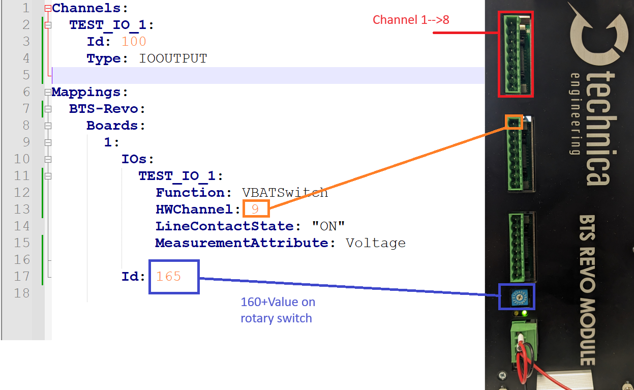
Map logical channel to a BTS-REVO
Id: the fourth byte of the IP of the CM. For example: IP CM 10.104.3.64 -> Id : 64.
HWChannel: Channel Id defined in the BTS Revo Web page.
MeasurementAttribute: Needed measurement: Voltage, Current, PWM (BTS Input Channel).
LineContactState: Open Load is by default active or not.
GndContactState: Short to GND is by default active or not.
VbatContactState: Vbat is by default active or not.
StaticChannel: The state of the channel is static, cannot be changed by test cases or test functions.
InitValue: depending on the channel type, this can be default resistance or voltage, etc.
Function: None, Relay, Potentiometer, ElectronicLoad, GNDSwitch, VBATSwitch, VoltageGenerator, etc.
ChannelType: IOOUTPUT or IOINPUT.
Map logical channel to a Serial Port
PortName: Serial Port name.
BaudRate: Serial port option to permit changing the baud rate.
Parity: Serial port option to permit changing the parity.
DataBits: Serial port option to permit changing the character size.
StopBits: Serial port option to permit changing the number of stop bits.
FlowControl: Serial port option to permit changing the flow control.
MessageTerminator: End of line char, used for the message termination detection like LF or CR (MessageTerminator: “rn”)
SeparationTimeMs: Time separating the send of two consecutive characters in the message in milliseconds.
Serial:
    Ports:
      Master-Serial:
        PortName: COM13
        BaudRate: 4000000
        Parity: None
        DataBits: 8
        StopBits: One
        FlowControl: None
        MessageTerminator: "" # Will be used to specify the message terminator:
                              # empty or ACSII character Or CR/LF Or LF/CR (default no terminator)
        MaxReceivedDataSize: 512
Map logical channel to HH Electrical load
HH electrical load is an external device used to simulate a load in a channel https://www.hoecherl-hackl.com/. Two types of devices were integrated: PLI series and PMLI series.
PortName: Serial Port name.
BaudRate: Serial port option to permit changing the baud rate.
Id: device id.
Type: PLI or PMLI (PMLI refers to multi-channel).
Channels: map a channel to the channel index.
HH_Electrical_load:
    Devices:
        1:
          Id: 1
          PortName: COM9
          Type: PMLI
          BitRate: 115200
          Channels:
            1:
                Id: 1 # channel_index
                Name: channel_name
Map logical channel (Antenna) to an LF_Reader
New LF_reader is an extension board for BTS revo it has a maximum 3 antenna by board.
BoardId: The board with LF_reader extension id.
Antennas: Define which channel of the LF_reader each antenna is connected to:
AntennaNumber: The number of antennas.
HWchannel: The channel of the LF_Reader.
Lf_Reader:
    1:
      BoardId: 169
      Antennas:
          1:
              AntennaNumber: 1
              HWChannel: 1
          2:
              AntennaNumber: 2
              HWChannel: 2
          3:
              AntennaNumber: 3
              HWChannel: 3
Map RelayBoards Channels (Technica Relay Board “SHS”)
The relay board is a component with several relays (electrically operated switch) that allows us to control their behavior and perform several additional actions.
The fields are:
CANChannelName: Name of the CAN channel connected to the Relay boards CAN bus.
Boards: List of relay boards connected.
Id : Mandatory board Id.
Relays: List of relay channels in the board.
- RELAY_NAME:
HWChannel: Channel id in the relay.
InitValue: Optional default OFF , possible values are: ON and OFF.
DefaultValue: Optional default OFF, possible values are: ON and OFF.
Function: Relay.
RelayBoards:
        CANChannelName: RELAY_BOARDS_CAN
        Boards:
            1:
                Id: 1
                Relays:
                  RELAY_A:
                    HWChannel: 1 # mandatory ( starting from 1  )
                    Function: Relay
            2:
                Id: 2
                Relays:
                  RELAY_B:
                    HWChannel: 1
                    InitValue: ON
                    DefaultValue: ON
                    Function: Relay
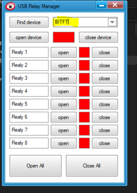
Map HIDRelayBoards Channels (DCTTECH manufacturer)
This section is a map of relay boards where the key is a unique int global id and the value is the board definition as in the following:
ID: Mandatory field, it contains the board serial (can be obtained via the TestApp using Find device button)
Relays: List of relay channels in the board.
RELAY_NAME:
HWChannel: Channel id in the relay.
InitValue: Optional default OFF , possible values are: ON and OFF.
DefaultValue: Optional default OFF, possible values are: ON and OFF.
HIDRelayBoards:
    1:
        ID: Board1Id
        Relays:
            RELAY_C:
                HWChannel: 1
                InitValue: ON
                DefaultValue: OFF
            RELAY_D:
                HWChannel: 2
    2:
        ID: Board2Id
        Relays:
            RELAY_E:
                HWChannel: 8
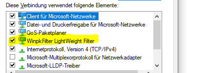
Map WinpkFilter Channels
To configure WinpkFilter channels, a section WinpkFilter should be added. It should contain a list of channels, each of them can be configured as the following:
CHANNEL_NAME
AdpaterFriendlyName : The name of the corresponding Ethernet Adapter.
Type: The type of the channel (possible values are: Filter, FilterFastIO).
IPMacTable : The list of couples of IP and its desired MAC.
IPV4Ttl: The IPV4Ttl value to be used for all outgoing IPV4 packets.
VLans:
- InnerTags and/or OuterTags: The list of Vlans (and or or).
ID: The Vlan Id (integer).
Priority: The Vlan Priority (integer).
IPList: The list of IP addresses to be assigned to this Vlan.
WinpkFilter:
    WinpkFilterTestChannel1:
        AdpaterFriendlyName: TestAdapter1
        Type: Filter
        IPMacTable: [[160.48.199.57, 00:00:00:00:00:39],[160.48.199.100, 00:00:00:00:00:64]]

    WinpkFilterTestChannel2:
        AdpaterFriendlyName: TestAdapter2
        Type: Filter
        VLans:
            InnerTags:
                -
                    ID: 68
                    Priority: 1
                    IPList: [160.48.199.57, 160.48.199.100]

            OuterTags:
                -
                    ID: 19
                    Priority: 7
                    IPList: [160.48.199.57]
        IPV4Tl: 1
To use this feature, the Windows Packet Filter driver needs to be installed and activated in the adapter. Releases · wiresock/ndisapi (github.com)
Note
It is recommended to deactivate it in all other adapters that are not using this feature.
Map TUN/TAP Bridge Channels
The TUN/TAP functionality enables you to bridge multiple virtual adapters with a physical adapter. This functionality allows for specific alterations to packet data at the bridging level. The update involves adding Vlan tags to packets transferred from the virtual to the physical adapter. In the other direction, the change consists of removing any Vlan layers from the packet and orienting the packet to the proper target virtual adapter.
To configure the TUN/TAP functionality, define an Ethernet channel with the bridge type in the list of channels, as shown below:
Channels:
 ETH_Bridge:
  Id: 90
  Type: BRIDGE
Then, the TUNTAP_BRIDGE mappings should be defined under the Mappings config section, linking the list of virtual adapters and the physical adapter under the same Ethernet bridge channel.
Mappings:
    TUNTAP_BRIDGE:
      ETH_Bridge:
        Name: ETH_Bridge
        PhysicalAdapter: Ethernet adapter
        TunTapAdapterList:
          TunTapAdapter:
            Name: Virtual_tap1
            InnerVlan:
              VlanId: 0x12
              VlanEthertype: 0x8100
              VlanPriorityTag: 0
              VlanCfi: true
            OuterVlan:
              VlanId: 0x34
              VlanEtherType: 0x9100
              VlanPriorityTag: 0
              VlanCfi: false
Name: Indicates the name of the Ethernet bridge channel.
PhysicalAdapter: Represents the friendly name of the physical adapter that will be associated with the virtual adapters.
TunTapAdapterList: Provides a list of virtual adapters that will be linked to the physical adapter of the specified Ethernet bridge channel.
TunTapAdapter: Specifies a configuration section for a single virtual adapter.
Name: The friendly name of the virtual adapter.
InnerVlan: The inner Vlan configuration section for the particular virtual adapter.
OuterVlan: The outer vlan configuration section for the particular virtual adapter.
VlanId: The ID field value for the current VLAN configuration section.
VlanEthertype: The ethertype value for the current VLAN configuration section. It is used to specify the VLAN standard.
VlanPriorityTag: Represents the priority field value for the current VLAN config section.
VlanCfi: IThe value of the VLAN CFI flag in relation to the current VLAN configuration section.
The TUN/TAP feature can be combined with a packet manipulation feature, which is responsible for VLAN tagging and changing the source mac address of packets that are sent dynamically (rather than statically, where the Vlan tags are static config for the virtual adapter) based on a configuration data set. This can be used with ManipulatePackets config option flag.
If the packet manipulation feature is left unspecified, it defaults to false. However, if it is set to true, the tagging process is based on the data set specified in the EthernetTopology config section, which is under the FrameworkConfig section within the EthernetConfig section. Therefore, defining the Inner and Outer Vlans configuration under the TunTapAdapter will be unnecessary.
Configuration of the time synchronization source (Time Server)
GrandMaster: Id of the EES responsible for the time synchronization
EES:
    GrandMaster: 200
FrameworkConfig
Tracers
Common fields for all the tracers
Type: Type of the Tracer PCAP, ASCII, etc.
TimeStamp: Timestamp precision, Microsecond or Nanosecond. It depends on the trace format for example: ascii supports only the microseconds precision and on the System capabilities Windows supports only Microseconds time-stamping. The tracer timestamp precision needs to match the configured network adapter timestamp to avoid any logging problem.
PCAP Tracer configuration
LoggingType: MultipleAdapterMode: log the traffic of several adapters in the same pcapng file. PerformanceMode: when performance is needed, several buffers, writing packets by block, etc.
Extension: File extension (optional).
BufferSize: Size of buffer to be used to buffer the received packets.
Note
Additional fields are needed for the PerformanceMode logging:
BufferNumber: Number of buffers to be used to buffer the received packets.
WriteBurstSize: Writing bytes to the file is done by blocks, this filed defines the size of one block.
BaseFileName: Rotating policy: Base file name (trace_eth_1, trace_eth_2, trace_eth_3, etc.), should be unique by tracer.
MaxFile: Rotating policy: Maximum number of files generated by the tracer.
MaxFileSize: Rotating policy: The tracer rotates log events when the size of the current log file exceeds the defined limit ‘MaxFileSize’ (MByte). The tracer will then create a new log file for further log events.
Note
If an application packet loss is detected, you may need to modify the Pcap logger configuration by increasing the BufferSize or the BufferNumber or even change the Pcap logger type (e.g. from MultipleAdapterMode to PerformanceMode).

Tracing:
    PCAP_Tracer_1:
        Type: PCAP
        LoggingType: MultipleAdapterMode
        Timestamp: Microsecond
        LoggerConfiguration:
            BufferConfig:
                BufferSize: 200
            FileConfig:
                Extension: ".pcapng.zst"
                CompressionLevel: 5
    PCAP_Tracer_2:
        LoggerConfiguration:
            BufferConfig:
                BufferNumber: '4'
                BufferSize: '128'
                WriteBurstSize: '128'
            FileConfig:
                Extension: trace_2
                Extension: .pcap
                MaxFileSize: '1024'
        LoggingType: PerformanceMode
        Timestamp: Microsecond
        Type: PCAP
ASCII Tracer configuration
Base: Hex or Decimal formatting.
InternalEventLogged: internal events like LIN wake-up request. More details can be found in the ASCII format specification.
Extension: File extension (optional).
BaseFileName: Rotating policy: Base file name (trace_eth_1, trace_eth_2, trace_eth_3, etc.). It should be unique by tracer.
MaxFile: Rotating policy: Maximum number of files generated by the tracer.
MaxFileSize: Rotating policy: The tracer rotates log events when the size of the current log file exceeds the defined limit ‘MaxFileSize’ (MByte). The tracer will then create a new log file for further log events.
TimeStampSetting: Absolute or Relative (to the start of the test case) timestamps.
default_ascii_tracer:
  Base: Hex
  InternalEventLogged: 'true'
  LoggerConfiguration:
    FileConfig:
      BaseFileName: lin_can_trace
      Extension: .asc
      MaxFile: '150'
      MaxFileSize: '200'
  TimeStamp: Microsecond
  TimeStampSetting: Absolute
  Type: ASCII
If you would like to test ASCII Tracer on a local computer, you need to add the channel that uses the ASCII Tracer to VirtualDevices.
CAN_channel1:
 Id: 45
 Type: CAN
 LoggingName: Debug-CAN
 TracerName: Default_Ascii_Tracer
CAN_channel2:
Mappings:
    VirtualDevices: Hex
        Buses: 'true'
            CAN_channel1:
                Name:
    PCAP:
        1:
ConnectedEcus (DUT’s)
List of Devices under test connected to the Test bench. Names should match the ECU names defined in the NK (ARXML, DBC, LDF, FIBEX).
FrameworkConfig:
  ConnectedEcus:
    - ECU1
    - ECU2
    - ECU3
Publisher Configuration
MTF (Modular Test Framework) implements a Publish/Subscribe Model for the events dispatching. For example: received CAN frames.
PublisherType: SingleThreaded: only one thread will be used for the dispatching of all types of events, or MultiThreaded: several threads will be used for the events dispatching.
ChannelsGroups: Define the threads/channels mapping.
FrameworkConfig: # optional
    PublisherConfig:
        PublisherType: MultiThreaded
        ChannelsGroups: # only relevant for MultiThreaded
            - [Ch_CAN1, Ch_CAN2, Ch_CAN3]
            - [ETH_SPY]
Ethernet Configuration
It contains 3 different optional configurations :
NPduConfig
ManangeVlansInCom: 802.1Q Vlan tag will be added to the NPDU packets sent via com layer based on the Database.
IPMacTable: List of couples of IP and its desired MAC.
VLans:
InnerTags and/or OuterTags: List of Vlans.
ID: Vlan Id.
Priority: Vlan Priority.
IPList: List of IP addresses to be assigned to this Vlan.
SomeIPConfig
ServerToClientPortRangeMapping:
ServerPorts: List of server ports ranges
ClientPorts: List of the corresponding client ports ranges
AppLayerPorts
It is a list of ports and/or ports ranges of the following App layer protocol : NPdu, SomeIp, UDPNM, DLT, SomeIpSD
EthernetConfig:
    NPduConfig: # optional
        VLans: # optional
            InnerTags:
                -
                    ID: 68 # Mandatory
                    Priority: 1 # Mandatory
                    IPList: [160.48.199.57, 160.48.199.100] # Mandatory
            OuterTags:
                -
                    ID: 19 # Mandatory
                    Priority: 7 # Mandatory
                    IPList: [160.48.199.57] # Mandatory
                -
                    ID: 20 # Mandatory
                    Priority: 1 # Mandatory
                    IPList: [160.48.199.100] # Mandatory
    # optional
    SomeIPConfig:
        # optional
        ServerToClientPortRangeMapping:
         # Mandatory
          ServerPorts: [[30501,30599], [31501,31599], [32501,32599]]
          # Mandatory
          # must have the same length as ServerPorts
          ClientPorts: [[30491,30499], [31491,30499], [32491,32499]]
    AppLayerPorts: # optional
        NPdu: [3000, [3100, 3200], 3208] # optional
        SomeIp: [[500, 503], 1000] # optional
        UDPNM: [4100] # optional
        DLT: [5000, 5001] # optional
        SomeIpSD: [30490] # optional
EthernetTopology
EthernetTopology defines the list of ethernet ECUs and their respective data (such as source MAC address, IP addresses list, VLANs) which will participate in sending communication to the DuT and the priority field value for the DuT VLAN for each ethernet packet type. The packet manipulation feature currently receives its data sets from this data configuration section. Below is a description about the EthernetTopology configuration section:
EthProtoPrioTable: A table in which we list priority field of each Ethernet protocol for the DuT VLAN layer. We currently only support ICMPv6, TCP and UDP.
TopologyConfig: A list in which every ecu configuration data is specified.
EcuName: The ecu’s name to which this configuration applies.
SrcMacAdr: The source mac address this ecu uses for communication.
SrcIpList: A list of the IP addresses this ecu uses.
OuterVlanTag/InnerVlanTag: Represent a vlan layer tag option.
Id: Represents the current VLAN configuration section’s ID field value.
Ethertype: is used to define the VLAN standard for the present VLAN configuration section. The following are the supported Ethertype :
IEEE 802.1Q EtherType 0x8100 for InnerVlanTag.
IEEE 802.1ad EtherType 0x88a8 and IEEE 802.1 q-in-q EtherType 0x9100 for OuterVlanTag.
VlanPriorityTag: reflects the value of the priority field in the current VLAN configuration section.
VlanCfi: indicates the VLAN CFI flag’s value.
EthernetConfig:
    EthernetTopology:
        EthProtoPrioTable: [
            [TCP, 0],
            [UDP, 4],
            [ICMPv6, 0]
        ]
        TopologyConfig:
         -
          EcuName: PartionName1
          SrcMacAdr: 00:1b:63:02:01:00
          SrcIpList: [
            fd53:7cb8:383:2::10f,
            2001:0db8:85a3:0000:0000:8a2e:0123:ACDE
          ]
          InnerVlanTag:
            Id: 0x3
            Ethertype: 0x8100
            VlanPriorityTag: 0
            VlanCfi: false
          OuterVlanTag:
            Id: 0x610
            Ethertype: 0x88a8
            VlanPriorityTag: 5
            VlanCfi: true
         -
          EcuName: PartionName2
          SrcIpList: [
            fd53:7cb8:383:5::e
          ]
          SrcMacAdr: 00:1b:63:84:45:e7
          InnerVlanTag:
            Id: 0x2
            Ethertype: 0x8100
            VlanCfi: false
          OuterVlanTag:
            Id: 0x610
            Ethertype: 0x88a8
            VlanPriorityTag: 4
            VlanCfi: true
ChannelToEcusMapping
This section links an ECU to its corresponding Ethernet transmission adapter via the physical channel name.
ChannelToEcusMapping:
    CHANNEL1: [ECU1, ECU2]
    CHANNEL3: [ECU3]
Diagnostics
This section is optional and it specifies protocol and addresses used for diagnostics sessions:
EcuIpAddress: IP address of the ECU to connect to. Can be left as “AutoDetect”.
TestersIpAddress: Tester address to use. It can be left as “Auto”. (Note: If the value is “Auto”, tester address cannot be manually changed in the diag session struct in C API)
Protocol: HSFZ or DOIP.
NetID: The Net address of the target ECU (Optional). If not specified, identification requests will be sent through all interfaces. If set, identification requests will only be sent through the specified net address.
FrameworkConfig: #optional
    Diagnostics:
        EcuIpAddress: AutoDetect # default AutoDetect or manually provided e.g "169.1.1.1"
        TestersIpAddress: 172.172.22.22 # default Auto or manually provided e.g "169.1.1.2"
        Protocol: DOIP # or HSFZ
        NetID: 160.48
ChannelsConfig
Note
This section is optional. More information will be provided in the future.
FaultyChannels
This section is used to define IO channels used to provoke a fault in one the buses or IO’s. For example: Short circuit in a CAN bus or Open wire in a LIN Bus.
ChannelsConfig:
    Io_Channel_Ex1:
        FaultyChannels: {keyFaultyType, valueIoHwChannel}
    Io_Channel_Ex2:
        FaultyChannels: {keyFaultyType, valueIoHwChannel}
Important notes
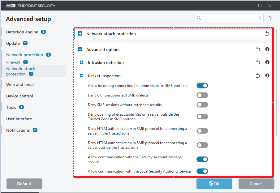
Important
By default, antivirus solutions inspect outgoing and incoming Ethernet traffic in our systems to detect potential threats.
It is very important to disable such services and turn off any kind of network protection in your Test System to prevent any performance impact if you are using hardware modules such as CMs, BTSRevo Boards, EES, etc.
Such changes in the Test System need to be done only by the IT team