Rest bus simulation CAN User Interface
Contents
Prerequisites
Create a new project.
Configure the Hardware device(s).
Import a database (CAN)
Creating nodes by Drag and Drop
After adding a CAN database, drag and drop (an) ECU(s) to the Nodes element.
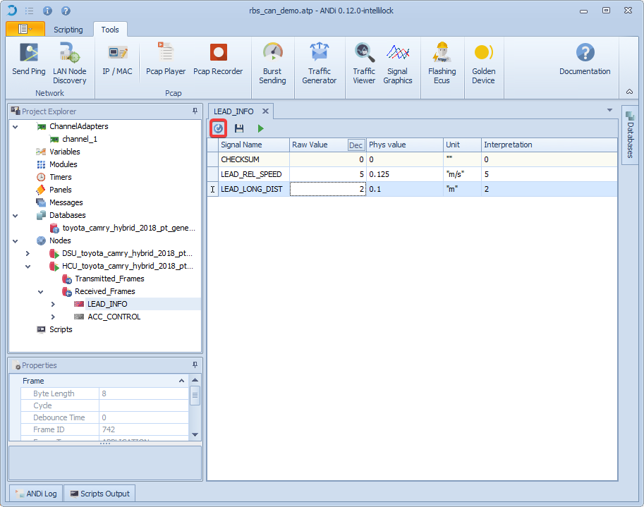
Transmitting a frame
1.Choose the frame to be sent
Before setting signals and sending a frame, you need to start the ECU and enable the frame to be sent.
2.Set and send signals
Every time a signal is set (by changing its value and pushing the enter button) a frame will be sent with the new values.
Generator
The generator is used to customize a signal's physical value. A predefined or customizable function will be followed by the latter over time. Using the Signal Graphics tool, the effects of adjusting the generator column are seen.
Generator Column
The generator column could be set to one of the following options:
Value When this option is selected, the generator will have no effect on the physical value of the signal. This option is selected by default.
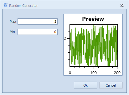
Random When this option is selected, a pop-up window would be displayed asking for Min and Max values. Once set, the generator would then change the physical value of the selected signal randomly while respecting the minimum and maximum values entered previously. The preview in the pop-up window would give an approximate estimation of what the signal's output might look like in the Signal Graphics tool.
Sinusoidal Wave Choosing this option and filling the Min, Max, Phase, and Frequency fields make the generator force the physical value signal to follow a sinusoidal wave function. A preview of a cycle of that function would be displayed.

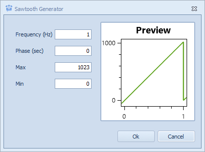
Sawtooth This option makes the physical value signal follow a sawtooth wave. In order for it to function properly, the Min, Max, Phase, and Frequency fields must be filled. The preview illustrated in the pop-up shows an approximation of what the generator will make the physical value signal look like.
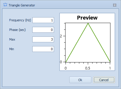
Triangle To make the signal output of the physical value follow a triangle function, this option should be selected. A preview of the one cycle of the function is displayed with the default values of the function's parameters (Min, Max, Phase, and Frequency). The preview will change once the default values are changed to the desired ones.
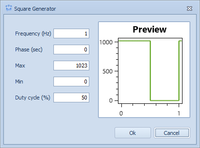
Square Selecting this option means making the signal output of the physical value follows a square wave shape. A preview containing the shape of a single cycle will be displayed once the Duty cycle, Min, Max, Phase, and Frequency values are configured. Otherwise, it will display a default shape according to the default values.
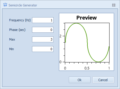
Semicircle The semicircle function option makes the signal output, if configured, follow a semicircle periodic wave. One cycle of the wave is displayed automatically with the default values. To configure it properly, Min, Max, Phase, and Frequency fields should be adapted as desired.
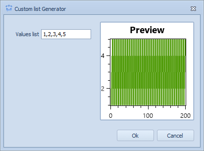
Custom List This option requires the use of a list of values. The values entered should be separated by a comma "," in order for the list to be recognized. The physical signal output will iterate on the values list one by one, while respecting the order they were introduced in. An illustration of some cycles that the function would follow would be presented in the pop-up window.
Equation In order to customize the physical value of a specific signal according to a specific function, this option should be chosen. It would require entering the lowest and highest values of the desired function (Min, Max) and the equation that the physical value should follow. The preview in the pop-up window will provide an approximate estimate of the output of the signal in the system.
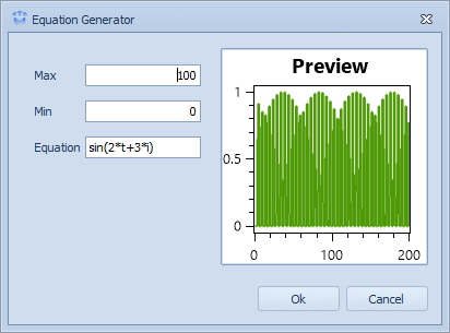
To customize the equation, a specific syntax should be respected. The equation should define a function depending on, at most, two variables "t" and "i" where "t" represents time and "i" represents the index of the message. The following table contains possible operators and functions that could be used in the definition of the equation:
Keywords |
Description |
Example |
|---|---|---|
+ |
Addition |
a+b |
- |
Subtraction |
a-b |
* |
Multiplication |
a*b |
/ |
Division |
a/b |
^ |
Exponentiation |
a^b |
# |
Modulo Function |
a#b |
sin |
Sine Function |
sin(t) |
cos |
Cosine Function |
cos(t) |
tan |
Tangent Function |
tan(t) |
abs |
Absolute Function |
abs(t) |
sqrt |
Square Root Function |
sqrt(t) |
sec |
Secant Function |
sec(t) |
Receiving a frame
To properly receive a frame, the ECU should already be started and the received frame enabled. Every time a frame with the same name/id from another ECU is sent over the network, the new values will automatically be received and set in the interface.
Save a frame
To save a frame and use the saved values as default every time the project is opened, click on Save Button.
Only transmitted frames could be saved.

Reset a frame
To reset a frame to the default values in the database, click on Reset Button.
Only transmitted frames could be reset. To reset a received frame, you need to reset a transmitted frame from another ECU.
Demonstration