General introduction to Capture modules
The Capture Modules are specialized devices designed to prevent the loss of retrieved messages in vehicle networks. They are available in five variants, each tailored to support different automotive protocols including CAN, CAN-FD, LIN, FlexRay, and various Ethernet standards. These modules ensure reliable message capture and timestamping across diverse bus topologies, facilitating comprehensive data logging and analysis.
CAN combo capture module
Initial steps
Before configurating the Capture module, some initial steps should be conducted:
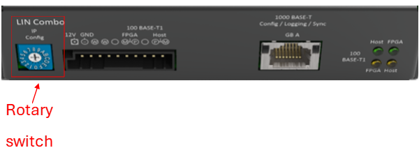
ID device check: The user should ensure that the provided ID module inserted on the bottom side of the Capture module box, corresponds to the last byte of the IP address of the Capture module.
Note
There are several types of hardware capture modules, for each one there are some IP address ranges that has been defined:
Rotary switch on 0 -> IP: 10.104.3.64
Rotary switch on 1 -> IP: 10.104.3.65
Rotary switch on 2 -> IP: 10.104.3.66
Rotary switch on E -> IP: 10.104.3.78
Rotary switch on F -> IP: 10.104.3.79 / Reset
Connecting to Power and PC: This step should be performed after verifying the Capture module’s ID and IP address. Then, connect the device to the power module and link the GB-A Ethernet port to the PC.
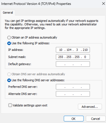
IP address check: As part of the verification, the user needs to check whether the IP address of the Ethernet adapter connected to the Capture module is within the same range as the Capture module’s IP address.
The first two numbers should belong to the same range. In this case, we are referring to 10.104.. However, the last number in the Ethernet IP address, which is 210, is different from the last number in the Capture module’s IP address, which is 64 as it is mentioned in the following images .
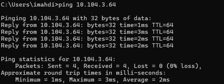
Capture module check: The user must perform a ping command to verify whether the device is reachable.
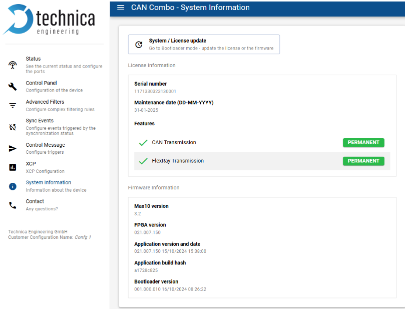
5. Platform access: Once the user ensures that the Capture module device is reachable, he (she) can access its web page. From there, he (she) can retrieves the relevant system information that needs to be verified, including the latest firmware version and the license.
After ensuring the initial steps of Capture module device validation are complete, the user begins setting up the channels. In the following tutorial, we will provide a clear explanation of how to arrange several protocol channel types, starting with the CAN/CAN-FD channels.
CAN/CAN-FD channel
Configuring the first CAN Channel
The user can configure their first CAN channel by following these steps:
Click on “status” on the Capture module web page.
Click on the first channel, for example: CAN-A.
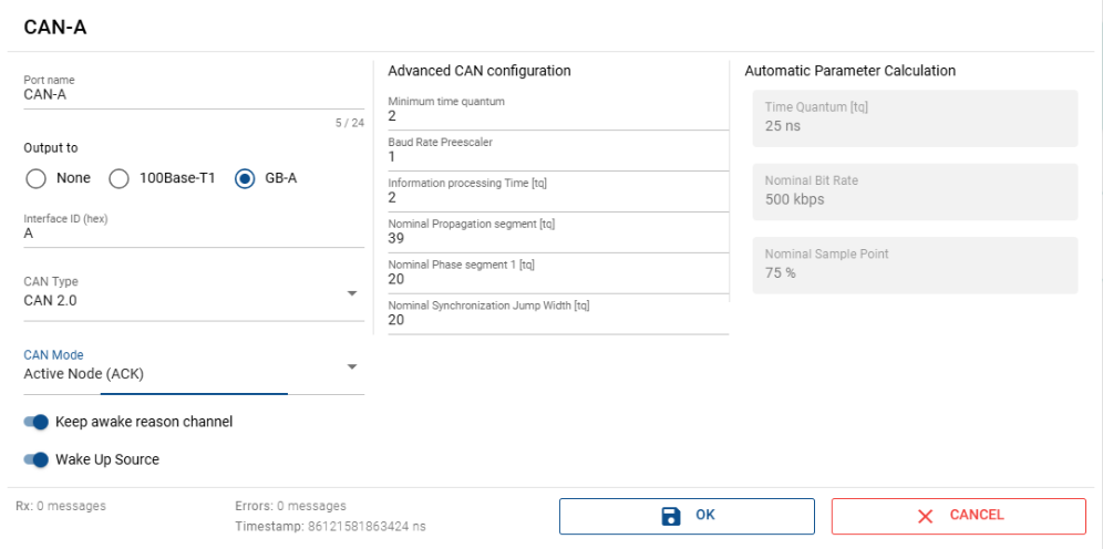
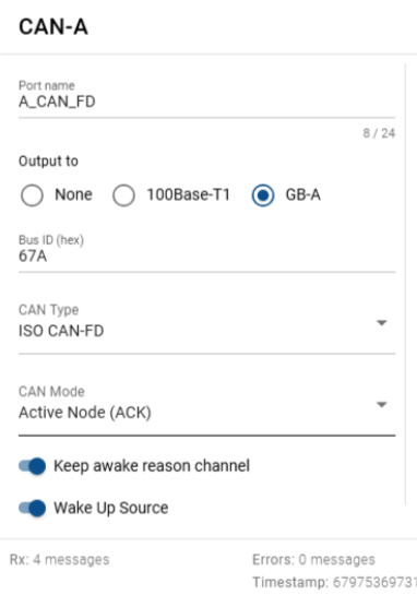
In the following web page window, some parameters can be specified:
The output port: The supported adapter that the Capture module uses for data traffic capture, for example the 100base T1 and GB-A(RJ45).
The interface ID: The logical ID used for the channel such as A.
The CAN type: The two types that could be used are either a CAN2.0, or ISO CAN-FD.
The Advanced CAN configuration: These parameters are used only when dealing with a nonstandard configuration, in which case the time quantum needs to be adjusted.
Configuring the CAN Capture module
As the user finalizes the configuration of the specific channel, it will be possible to start configuring the Capture module by clicking on “Spy” in the same status window of the web page.
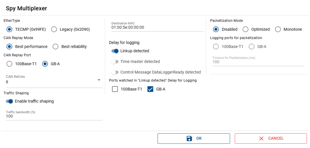
This SPY Multiplexer window appears, allowing the user to define the following important parameters:
EtherType selection: The user selects either TECMP or Legacy as the protocol version.
CAN Reply Mode selection: The user can choose between two options, Best performance or Best reliability.
Best performance: This mode is used when the bus is empty or when the requested frame has high priority. In such cases, the Capture module will attempt to send the frame as soon as possible. A frame may be dropped if the Capture module fails to send it after the maximum number of retries or if the CAN buffer in the Capture module is full.
Best reliability: In this mode, the Capture module does not drop the frame, but transmission may be delayed if one channel is unable to send or its buffer is full. In such a case, all other channels will also be blocked.
Note
For general purpose use, the recommended mode is Best performance.
However, in some specific scenarios such as when only one channel is used for the Capture module,
or when there is prior knowledge concerning the frame transmission load and dispatch during the execution.
CAN Replay port selection: The user selects the replay data source port from which the data is retrieved.
CAN retries specification: This parameter is validated only for Best performance mode; it defines the maximum number of retries that the Capture module will do before dropping the frame.
Packetization mode specification: This mode allows CAN/FlexRay events to be grouped into a single packet. However, this feature is not supported in the current version of the driver, so it is recommended to disable it.
Configuring the Capture module port
For configuring the Capture module communication port, the user can click on the “GB-A” in the same status window on the web page.
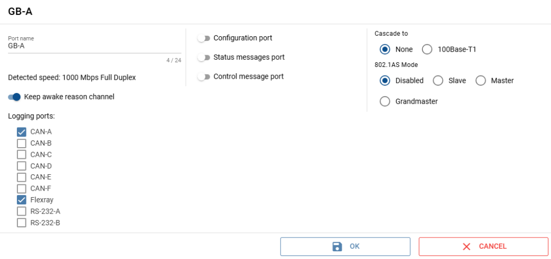
The different channels used for logging are also displayed. The user has the option to enable the configuration, status, and control message ports. Additionally, the user can activate the option to keep the reason channel awake. The frame can be transferred to the 100BASE-T1. The detected speed of frame transfer is also indicated as 1000 Mbps. Moving to the next important parameter in the same window, which is the 802.1AS mode: In this case, it is disabled. However, there are other modes, such as Master or Slave, which relate to the PTP sync mode. In these cases, another node will sync our device (Slave mode) or the grandmaster mode, indicating that the Capture module in use will sync other devices.
After completing the web configuration, it’s now time to configure the YAML file for MTF CAN.
In this guide, we will provide an example to make the process clearer for the user:
Configuring the YAML file for MTF CAN
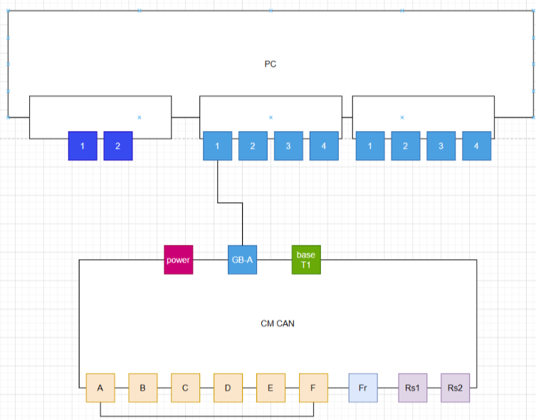
The test bench used as an example has only one Capture module with ID 67. For its connected logging ports, CAN-A is connected to CAN-F like like it is presented in the following configuration.
Note
The user must ensure that both the Capture module and the corresponding YAML configuration file define the CAN FD frame to be transmitted, even though the protocol and CAN type are technically independent.
Test Cases
When using XTR, the test bench must include at least the TestBase class, which contains the setUpClass and tearDownClass methods.
These methods are executed by XTR before running the full set of test series defined in the XML file.
For more information, please refer to the XTR documentation links:
Conftest — MTF Documentation 1.30.0 documentation
Create a test series configuration file — MTF Documentation 1.30.0 documentation
The user needs to run the XTR execution command to run the test case, as defined in the corresponding documentation:
First CAN-FD-Transmission Test-case
In this step, after configuring the YAML file, the user can start implementing the first test case based on the usage of the ARXML database, provided in the MTF basic tuto project presented in this link:
Tutorials – Technica Engineering,
after converting it to a db file using Databex, for more information please check this link:
DataBex — MTF Documentation 1.30.0 documentation
from test_base import TestBase
mtf_base = MtfBase()
from time import sleep
from xtr import logging, Severity
logger = logging.getLogger(__name__)

# Create the test case class, that inherits from the preset FixtureFramesCapture class.

class TestCaptureCanFdFrames(TestBase):

    # Create setUp method.

    def setUp(self):

        logger.info("Setup test case")

    # Create the tearDown method.

    def tearDown(self):

        logger.info("Tear down test case")

    # Create the test case method that holds the main test steps.

    def test_capture_can_fd_frames(self):
        """

        Test the setting of the physical signal value

        and then verify that it was set correctly by checking

        the last value in the listener's queue

        """
        #get the channel by its name
        channel = mtf_base.com_network.try_get_channel_by_name("CLUSTER1")

        #verify that the channel exists
        assert channel is not None

        # start listening on that channel on a specific
        # frame(having the id 0x46d)
        mtf_base.can_frame_listener("CLUSTER1",0x46d).start_listening()

        # start the transmission of that cyclic frame
        channel.get_frame_by_id(0x46d).start_transmission()

        sleep(3)

        #set the physical/raw value of a specific signal of that frame
        channel.get_frame_by_id(0x46d).get_signal_by_name(
            "SIGNAL1_FRAME1").set_physical_value(4)

        sleep(0.5)

        # stop the listening on that channel
        mtf_base.can_frame_listener("CLUSTER1",0x46d).stop_listening()

        # get the queue of the frames captured
        Frames = mtf_base.can_frame_listener("CLUSTER1",0x46d).get_queue()

        payload_list = []

        for frame in frames.queue:
            payload_list.append(frame.payload)

        #verify that there was not issue while transmitting or listening

        self.assertTrue(frames.qsize()!= 0,
                          Severity.BLOCKER,
                        "****Error Queue should not be empty")

        last_payload = payload_list[-1]
        # The original payload was a list of 0xff here in the expected
        # we can notice the change in one of the bytes with the value
        # that we have set.

        expected_payload = [0xff, 0xff, 0xff, 0xff, 0xff, 0x04, 0xff, 0xff,
                            0xff, 0xff, 0xff, 0xff, 0xff, 0xff, 0xff, 0xff,
                            0xff, 0xff, 0xff, 0xff, 0xff, 0xff, 0xff, 0xff,
                            0xff, 0xff, 0xff, 0xff, 0xff, 0xff, 0xff, 0xff,
                            0xff, 0xff, 0xff, 0xff, 0xff, 0xff, 0xff, 0xff,
                            0xff, 0xff, 0xff, 0xff, 0xff, 0xff, 0xff, 0xff
                        ]

        # verify that the last frame received has the same value as expected
        # after setting the signal
        self.assertTrue(last_payload == expected_payload, Severity.BLOCKER,
                        "Signal Value is not received as expected")
First CAN-Transmission Test-case
Since we are using a database, we need to use the same channel in the YAML configuration file as the one defined in the database.
from test_base import TestBase
from mtf.mtf_base import MtfBase
mtf_base = MtfBase()
from time import sleep
from xtr import logging, Severity
logger = logging.getLogger(__name__)
from mtf.network_port.frames.can_frame import CanFrame

class TestCaptureCanFrames(TestBase):

    # Create setUp() method.
    def setUp(self):
        logger.info("Setup test case")

    # Create the tearDown() method.
    def tearDown(self):
        logger.info("Tear down test case")

    # Create the test case method that holds the main test steps.
    def test_tc_capture_can_frames(self):
        """
        Test the setting of the physical signal value
        and then verify that it was set correctly by checking
        the last value in the listener's queue
        """
        #get the channel by its name
        channel = mtf_base.com_network.try_get_channel_by_name("CLUSTER1")

        #verify that the channel exists
        assert channel is not None


        # create a instance of can frame for the frame having
        # channel name 'CLUSTER1' and the frame_id '0xa7'
        can_frame = CanFrame("CLUSTER1",0xa7)

        # start the transmission of the cyclic frame
        can_frame.start_transmission_frame()

        # start listening on that channel on taht specific
        # frame(having the id 0xa7)
        listener = can_frame.listener
        listener.start_listening()

        sleep(3)

        #set the value of a specific signal of that frame to 4
        channel.get_frame_by_id(0xa7).get_signal_by_name(
            "FRAME3_0").set_physical_value(4)

        sleep(2)
        last_received_payload = can_frame.get_last_received_frame()

        expected_payload = [0x04, 0xff, 0xff, 0xff, 0xff, 0xff, 0xff, 0xff]

        # verify that the last frame received has the same value as expected
        # after setting the signal
        self.assertTrue(last_received_payload == expected_payload, Severity.BLOCKER,
                        str(last_received_payload))
There are two possible outcomes when executing test cases: If the test passes, everything is fine; otherwise, a failure may be due to a connection or configuration issue.
This configuration is being verified through using the filter “tecmp.message_type == 0x0a” in Wireshark to check whether the expected request appears indicating that the YAML configuration is correct.

If the problem is not related to the configuration, it could be a hardware issue so a check, should be performed and which includes the verification of the license and the CAN mode for both CAN-A and CAN-F connected logging ports should be set to Active mode,
added to that, checking the CAN wiring and confirming that the termination resistor is properly connected.
Check license
CAN mode (Active Node) for both CAN-A and CAN-F
FLEXRAY channel
Configuring the first FlexRay Channel
The user can configure their FlexRay channel by following these steps:
Click on “status” on the Capture module web page.
Click on the FlexRay channel.
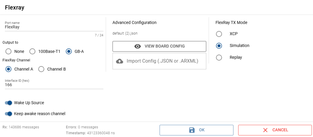
In the following web page window, some parameters can be specified:
The output port: The supported adapter that the Capture module uses for data traffic capture, for example the 100base T1 and GB-A(RJ45).
The Flexray channel type: : Either it is defined as channel A or channel B.
The interface ID: The logical ID used for the channel.
The Flexray parameter: The designed ARXML or JSON which has this parameter like the gNumberOfStaticSlots and gPayloadLengthStatic.
The FlexRay Tx mode: The Capture module supports different modes, but the driver supports only simulation mode.
Since our Capture module supports only one FlexRay channel in this case, we require two CAN Capture modules.
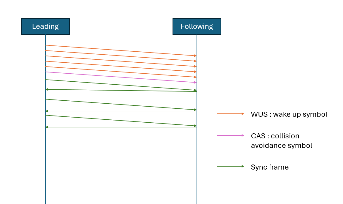
For FlexRay communication, a minimum of two nodes is necessary: one leading node and one following node.
The leading node is responsible for initiating the communication by:
Wake-Up Phase
When the FlexRay bus is idle (i.e., in sleep mode), one or more nodes transmit a Wake-Up Pattern.
This pattern is not a message, but a specific electrical signal placed on the bus to wake the system.
All ECUs that detect this pattern exit sleep mode and enter the ready state.
Note
Sent by: Any node configured to support wake-up (can be multiple).
CAS (Collision Avoidance Symbol)
When multiple nodes are eligible to initiate network communication, a CAS (Collision Avoidance Symbol) is used to prevent clashes.
A node intending to initiate communication sends a CAS. Upon detecting the CAS, other cold-start-capable nodes defer their own start attempts.
Note
Sent by: Cold Start Node (Leading Node candidate).
Cold Start Procedure
The Cold Start Node transmits Sync Frames in predefined Key Slots to signal the start of the communication cycle. The following Nodes then respond with their own Sync Frames.
In our system, we must identify the type of node connected to correctly configure the FlexRay bus.
Let’s take as example the following Test Bench connection:
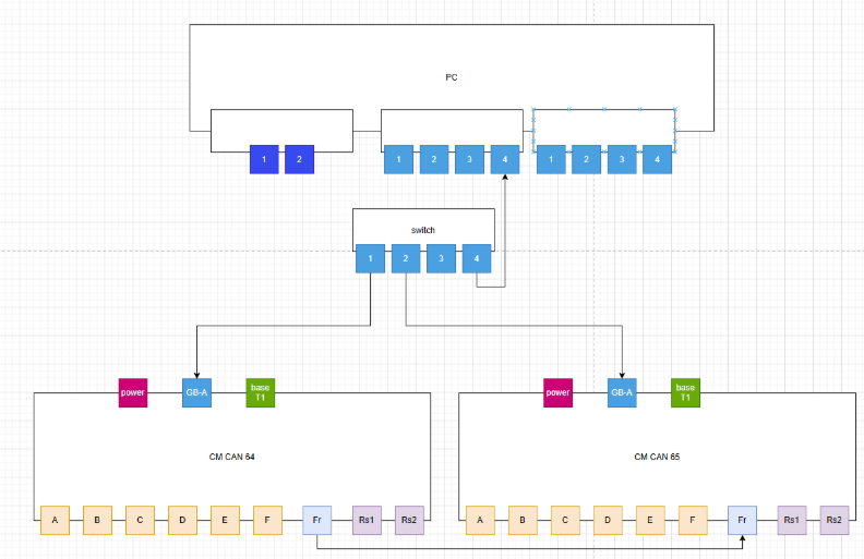
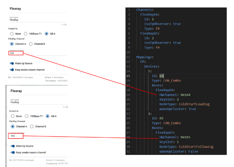
We will configure the Capture module 64 flexray channel to be our leading node and the Capture module 65 FlexRay channel to be our following node.
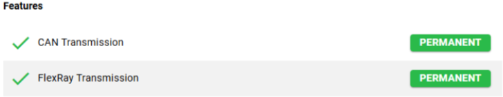
Additionally, as with the CAN license, the FlexRay license must also be verified.
Check license
FlexRay Test-case
from test_base import TestBase
from mtf.mtf_base import MtfBase
mtf_base = MtfBase()
from time import sleep
from xtr import logging, Severity
logger = logging.getLogger(__name__)
from mtf.enum_types import BusType, TransmissionMode, FRCommunicationChannel
from mtf.enum_types import Direction

# Create the test case class, that inherits from the preset TestBase class.
class TestCaptureFlexrayFrames(TestBase):

    # Create setUp() method.
    def setUp(self):
        logger.info("Setup test case")

    # Create the tearDown() method.
    def tearDown(self):
        logger.info("Tear down test case")

    # Create the test case method that holds the main test steps.
    def test_capture_flexray_frames(self):
        """
        Test the transmission of a flexray frame
        and then verify that it was received correctly
        by checking the listener's queue
        """
        # Start listening on the channel FlexRay65 and while filtering on the frame id 5.1.1
        mtf_base.flexray_frame_listener("FlexRay65", "5.1.1").start_listening(
            silent_mode=True,
            direction=Direction.Full
        )
        sleep(1)

        # Transmit the payload on the flexray channel FlexRay64 with the frame id 5.1.1
        mtf_base.bus_manager.bus_transmitter(BusType.FLEXRAY).transmit_frame(
            channel_name="FlexRay64",
            frame_id="5.1.1",
            payload=[0x1, 0x2, 0x3, 0x4, 0x5, 0x6, 0x7],
            communication_channel=FRCommunicationChannel.ChannelA,
            transmission_mode=TransmissionMode.SingleShot
        )
        sleep(1)

        # Stop the transmission
        mtf_base.bus_manager.bus_transmitter(BusType.FLEXRAY).stop_transmit(
            channel_name="FlexRay64",
            frame_id="5.1.1",
            communication_channel=FRCommunicationChannel.ChannelA
        )

        # Stop the listener
        mtf_base.flexray_frame_listener("FlexRay65", "5.1.1").stop_listening()

        # Get the queue
        queue_list = mtf_base.flexray_frame_listener("FlexRay65", "5.1.1").get_queue()

        # Check that flexray frames were received
        # (two frames are received: Rx frame and Tx frame
        # due to the direction "Full" that was set in start_listening)
        self.assertTrue(
            queue_list.qsize() == 2,
            Severity.BLOCKER,
            "Flexray Frames are not received"
        )